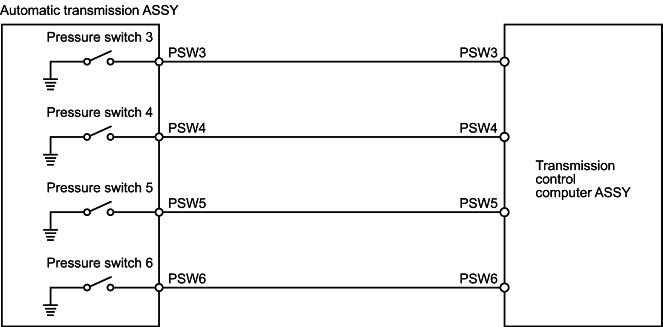
Eight pressure switches are installed in the valve body. The oil passages in the valve body are switched according to the operation status of each solenoid, each shift valve, and each control valve etc., and the pressure switches are switched ON or OFF. Pressure switch 3 operates according to the status of solenoid S1 and shift valve No. 1, pressure switch 4 operates according to the status of solenoid S2 and shift valve No. 2, pressure switch 5 operates according to the status of solenoid S3 and shift valve No. 3, and pressure switch 6 operates according to the status of solenoid S3 and shift valve No. 4. The transmission control computer ASSY puts out diagnostic codes when trouble occurs in this PSW3 signal system, PSW4 signal system, PSW5 signal system, PSW6 signal system, or in the solenoid or shift valve system.
| DTC No. |
|
Inspection part |
| P0751/45 |
|
|
| P0756/46 |
|
|
| P0761/47 |
|
|
| P0761/48 |
|
|
Detail
- Confirm output of P0973/62 [shift solenoid 1 trouble (Low)], P0974/62 [shift solenoid 1 trouble (High)], P0976/63 [shift solenoid 2 trouble (Low)], P0977/63 [shift solenoid 2 trouble (High)], P0979/64 [shift solenoid 3 trouble (Low)], P0980/64 [shift solenoid 3 trouble (High)], P0985/65 [shift solenoid 4 trouble (Low)] and P0986/65 [shift solenoid 4 trouble (High)] in addition to DTC P0751/54, P0756/46, P0761/47 and P0761/48.
Standard:
Inspection result Step Only output of DTC P0751/45, P0756/46, P0761/47 and P0761/48 To step A Output of DTC P0751/45, P0756/46, P0761/47, and P0761/48, as well as other diagnostic codes. To step B
In case of output of a diagnostic code other than DTC P0751/45, P0756/46, P0761/47 and P0761/48, perform trouble-shooting for that diagnostic code first.
B
To the related diagnostic code chart (refer to page for the outline)A
Proceed to [2]INSPECT TRANSMISSION CONTROL COMPUTER ASSY BY ITSELF (INSPECT VOLTAGE)
- Set the ignition switch to ON.
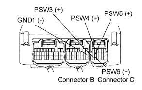
- Check the voltage between the terminals of the transmission control computer ASSY. (Refer to page for the terminal layout.)
Standard:
Terminal No.
(terminal symbol)Measuring condition Voltage [V] C17 (PSW3) ↔ B8 (GND1) P range
(Pressure switch 3 OFF)12-32 C5 (PSW4) ↔ B8 (GND1) Driving with gear 2
(Pressure switch 4 OFF)12-32 C11 (PSW5) ↔ B8 (GND1) Driving with gear 2
(Pressure switch 5 OFF)12-32 C16 (PSW6) ↔ B8 (GND1) Driving with gear 2
(Pressure switch 6 OFF)12-32
Repair or replace wire harness and connector.
Proceed to [3]INSPECT WIRE HARNESS AND CONNECTOR (TRANSMISSION CONTROL COMPUTER ASSY - TRANSMISSION WIRE)
- Disconnect connectors A and B of the transmission wire.
- Set the ignition switch to ON.
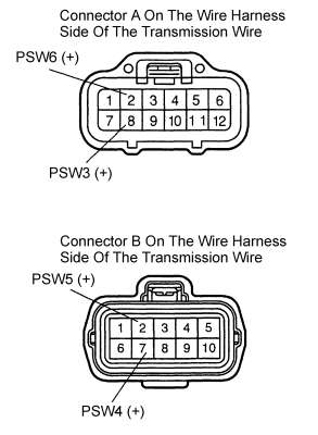
- Check the voltage between the terminals of the connector on the wire harness side of the transmission wire and body earth.
Standard:
Terminal No.
(terminal symbol)Measuring condition Voltage [V] A8 (PSW3) ↔ Body earth P range
(Pressure switch 3 OFF)12-32 B7 (PSW4) ↔ Body earth Driving with gear 2
Pressure switch 4 OFF)12-32 B2 (PSW5) ↔ Body earth Driving with gear 2
(Pressure switch 5 OFF)12-32 A2 (PSW6) ↔ Body earth Driving with gear 2
(Pressure switch 6 OFF)12-32
Repair or replace wire harness and connector.
Proceed to [4]INSPECT TRANSMISSION WIRE BY ITSELF (PSW3, PSW4, PSW5, PSW6)
- Disconnect the two transmission wires.
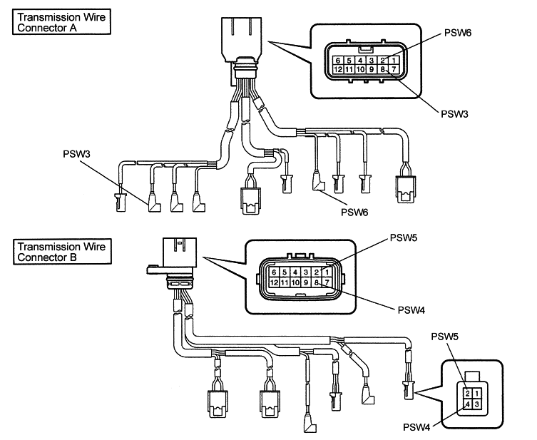
- Check for continuity between the terminals.
Standard:
Terminal No. (terminal symbol) Conductivity A8 (PSW3) ↔ PSW3 Yes B7 (PSW4) ↔ PSW4 Yes B2 (PSW5) ↔ PSW5 Yes A2 (PSW6) ↔ PSW6 Yes
Repair or replace the transmission wire.
Replace the automatic transmission ASSY.
- Confirm the DTC P0761/48 is inactive
- Start the engine and let it idling condition.
- Verify the DTC P0761/48 is inactive.
- DTC Clear
- Clear the DTC with Hino DX
- Confirm the same DTC is not reoccurred
- P0761/48 is reoccurF Return to first process
- Other DTC appearF Refer to concerned Trouble shooting
Complete