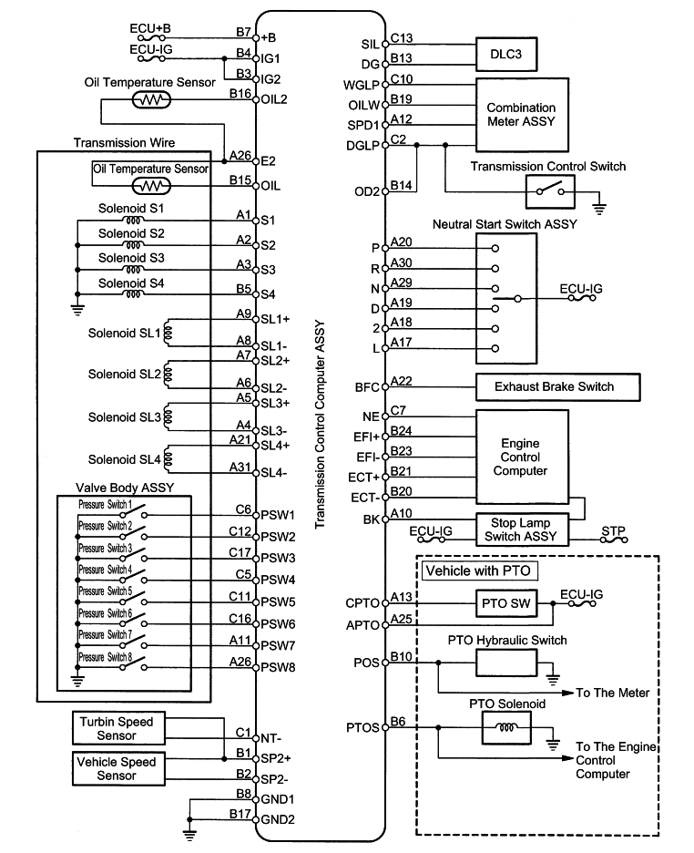
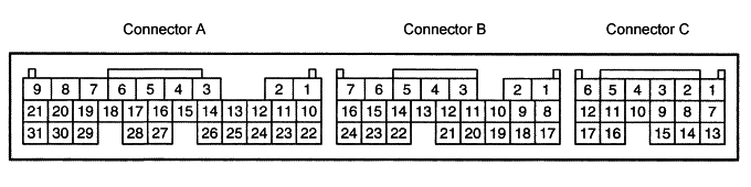
Terminal layout
| Terminal symbol [terminal No.] | I/O | Item | Measuring condition | Reference value |
| S1 ↔ GND1 [A1 ↔ B8] | Output | Voltage | Shift lever P range (pressure switch 3 OFF) | 0-3V |
| S1 ↔ GND1 [A1 ↔ B8] | Output | Voltage | Shift lever R range (pressure switch 3 ON) | 15-32V |
| S2 ↔ GND1 [A2 ↔ B8] | Output | Voltage | Shift lever P range (pressure switch 4 ON) | 15-32V |
| S2 ↔ GND1 [A2 ↔ B8] | Output | Voltage | Running with gear 2 (pressure switch 4 OFF) | 0-3V |
| S3 ↔ GND1 [A3 ↔ B8] | Output | Voltage | Shift lever P range (pressure switch 6 ON) | 15-32V |
| S3 ↔ GND1 [A3 ↔ B8] | Output | Voltage | Running with gear 2 (pressure switch 6 OFF) | 0-3V |
| SL3+ ↔ SL3- [A5 ↔ A4] | Output | Waveform | Engine at idle speed | Waveform 1 |
| SL2+ ↔ SL2- [A7 ↔ A6] | Output | Waveform | Engine at idle speed | Waveform 2 |
| SL1+ ↔ SL1- [A9 ↔ A8] | Output | Waveform | Engine at idle speed | Waveform 3 |
| BK ↔ GND1 [A10 ↔ B8] | Input | Voltage | Brake pedal depressed (switch ON) | 15-32V |
| BK ↔ GND1 [A10 ↔ B8] | Input | Voltage | Brake pedal released (switch OFF) | 0-3V |
| PSW7 ↔ GND1 [A11 ↔ B8] | Input | Voltage | Shift lever D range, vehicle stopped (pressure switch 7 ON) | 0-3V |
| PSW7 ↔ GND1 [A11 ↔ B8] | Input | Voltage | Shift lever P range, vehicle stopped (pressure switch 7 OFF) | 12-32V |
| SPD1 ↔ GND1 [A12 ↔ B8] | Input | Waveform | Running with vehicle speed 20 km/h | Waveform 4 |
| CPTO ↔ GND1 [A13 ↔ B8] | Output | Voltage | PTO switch ON | 15-32V |
| CPTO ↔ GND1 [A13 ↔ B8] | Output | Voltage | PTO switch OFF | 0-3V |
| L ↔ GND1 [A17 ↔ B8] | Input | Voltage | Shift lever L-3 range | 15-32V |
| L ↔ GND1 [A17 ↔ B8] | Input | Voltage | Shift lever other than L-3 range | 0-3V |
| 2 ↔ GND1 [A18 ↔ B8] | Input | Voltage | Shift lever 4 range | 15-32V |
| 2 ↔ GND1 [A18 ↔ B8] | Input | Voltage | Shift lever other than 4 range | 0-3V |
| D ↔ GND1 [A19 ↔ B8] | Input | Voltage | Shift lever D range | 15-32V |
| D ↔ GND1 [A19 ↔ B8] | Input | Voltage | Shift lever other than D range | 0-3V |
| P ↔ GND1 [A20 ↔ B8] | Input | Voltage | Shift lever P range | 15-32V |
| P ↔ GND1 [A20 ↔ B8] | Input | Voltage | Shift lever other than P range | 0-3V |
| SL4+ ↔ SL4- [A21 ↔ A31] | Output | Waveform | Engine at idle speed | Waveform 5 |
| BFC ↔ GND1 [A22 ↔ B8] | Input | Voltage | Exhaust brake switch OFF | 0-3V |
| BFC ↔ GND1 [A22 ↔ B8] | Input | Voltage | Exhaust brake switch ON | 15-32V |
| APTO ↔ GND1 [A25 ↔ B8] | Input | Voltage | Engine stopped, ignition switch ON | 15-32V |
| PSW8 ↔ GND1 [A26 ↔ B8] | Input | Voltage | Shift lever P range (pressure switch 8 OFF) | 12-32V |
| PSW8 ↔ GND1 [A26 ↔ B8] | Input | Voltage | Shift lever D range (pressure switch 8 ON) | 0-3V |
| E2 ↔ Body earth [B8] | - | Conductivity | Always | Conductivity |
| N ↔ GND1 [A29 ↔ B8] | Input | Voltage | Shift lever N range | 15-32V |
| N ↔ GND1 [A29 ↔ B8] | Input | Voltage | Shift lever other than N range | 0-3V |
| R ↔ GND1 [A30 ↔ B8] | Input | Voltage | Shift lever R range | 15-32V |
| R ↔ GND1 [A30 ↔ B8] | Input | Voltage | Shift lever other than R range | 0-3V |
| SP2+ ↔ GND1 [B1 ↔ B8] | Input | Voltage | Engine at idle speed | 7-9V |
| SP2- ↔ GND1 [B2 ↔ B8] | Input | Waveform | Running with vehicle speed 20 km/h | Waveform 6 |
| IG2 ↔ GND1 [B3 ↔ B8] | Input | Voltage | Engine stopped, ignition switch ON | 20-32V |
| IG1 ↔ GND1 [B4 ↔ B8] | Input | Voltage | Engine stopped, ignition switch ON | 20-32V |
| S4 ↔ GND1 [B5 ↔ B8] | Output | Voltage | Shift lever P range, engine at idle speed (pressure switch 8 OFF) | 15-32V |
| S4 ↔ GND1 [B5 ↔ B8] | Output | Voltage | Running with gear 2 (pressure switch 8 ON) | 0-3V |
| PTOS ↔ GND1 [B6 ↔ B8] | Output | Voltage | PTO switch ON | 15-32V |
| PTOS ↔ GND1 [B6 ↔ B8] | Output | Voltage | PTO switch OFF | 0-3V |
| +B ↔ GND1 [B7 ↔ B8] | Input | Voltage | Engine stopped, ignition switch ON | 20-32V |
| GND1 ↔ Body earth [B8] | - | Conductivity | Always | Conductivity |
| POS ↔ GND1 [B10 ↔ B8] | Input | Voltage | Engine stopped, ignition switch ON | 20-32V |
| DG ↔ GND1 [B13 ↔ B8] | Input | Voltage | DLC3 TC-CG short-circuited | 0-3V |
| DG ↔ GND1 [B13 ↔ B8] | Input | Voltage | DLC3 TC-CG open | 12-32V |
| OD2 ↔ GND1 [B14 ↔ B8] | Input | Voltage | Transmission control switch ON (gear 4 permitted) | 12-32V |
| OD2 ↔ GND1 [B14 ↔ B8] | Input | Voltage | Transmission control switch OFF (gear 4 prohibited) | 0-3V |
| OIL ↔ E2 [B15 ↔ A28] | Input | Voltage | Engine stopped, ignition switch ON | 0.1-4.9V |
| OIL2 ↔ E2 [B16 ↔ A28] | Input | Voltage | Engine stopped, ignition switch ON | 0.4-4.9V |
| GND2 ↔ Body earth [B17] | - | Voltage | Always | Conductivity |
| OILW ↔ GND1 [B19 ↔ B8] | Output | Voltage | AT oil temperature warning lamp lit | 0-3V |
| OILW ↔ GND1 [B19 ↔ B8] | Output | Voltage | AT oil temperature warning lamp not lit | 15-32V |
| ECT- ↔ GND1 [B20 ↔ B8] | Output | Waveform | Engine at idle speed | Waveform 7 |
| ECT+ ↔ GND1 [B21 ↔ B8] | Output | Waveform | Engine at idle speed | Waveform 8 |
| EFI- ↔ GND1 [B23 ↔ B8] | Input | Waveform | Engine at idle speed | Waveform 7 |
| EFI+ ↔ GND1 [B24 ↔ B8] | Input | Waveform | Engine at idle speed | Waveform 8 |
| NT- ↔ GND1 [C1 ↔ B8] | Input | Waveform | Engine at idle speed | Waveform 9 |
| DGLP ↔ GND1 [C2 ↔ B8] | Input | Voltage | Transmission control switch ON (gear 4 permitted) | 0-3V |
| DGLP ↔ GND1 [C2 ↔ B8] | Input | Voltage | Transmission control switch OFF (gear 4 prohibited) | 15-32V |
| PSW4 ↔ GND1 [C5 ↔ B8] | Input | Voltage | Shift lever P range, engine stopped (pressure switch 4 ON) | 0-3V |
| PSW4 ↔ GND1 [C5 ↔ B8] | Input | Voltage | Running with gear 2 (pressure switch 4 OFF) | 12-32V |
| PSW1 ↔ GND1 [C6 ↔ B8] | Input | Voltage | Shift lever P range, engine stopped (pressure switch 1 OFF) | 12-32V |
| PSW1 ↔ GND1 [C6 ↔ B8] | Input | Voltage | Running with gear 2 (pressure switch 1 ON) | 0-3V |
| NE ↔ GND1 [C7 ↔ B8] | Input | Waveform | Engine at idle speed | Waveform 10 |
| WGLP ↔ GND1 [C10 ↔ B8] | Output | Voltage | For 3 seconds after ignition switch ON (when the lamp is lit) | 0-3V |
| WGLP ↔ GND1 [C10 ↔ B8] | Output | Voltage | For 3 seconds after ignition switch ON (when the lamp is not lit) | 15-32V |
| PSW5 ↔ GND1 [C11 ↔ B8] | Input | Voltage | Shift lever P range, engine stopped (pressure switch 5 ON) | 0-3V |
| PSW5 ↔ GND1 [C11 ↔ B8] | Input | Voltage | Running with gear 2 (pressure switch 5 OFF) | 12-32V |
| PSW2 ↔ GND1 [C12 ↔ B8] | Input | Voltage | Shift lever R range (pressure switch 2 ON) | 0-3V |
| PSW2 ↔ GND1 [C12 ↔ B8] | Input | Voltage | Shift lever D range (pressure switch 2 OFF) | 15-32V |
| SIL ↔ GND1 [C13 ↔ B8] | Output | Waveform | When the SST is connected to DLC3 | Waveform 11 |
| PSW6 ↔ GND1 [C16 ↔ B8] | Input | Voltage | Shift lever P range, vehicle stopped (pressure switch 6 ON) | 0-3V |
| PSW6 ↔ GND1 [C16 ↔ B8] | Input | Voltage | Running with gear 2 (pressure switch 6 OFF) | 12-32V |
| PSW3 ↔ GND1 [C17 ↔ B8] | Input | Voltage | Shift lever P range (pressure switch 3 OFF) | 12-32V |
| PSW3 ↔ GND1 [C17 ↔ B8] | Input | Voltage | Shift lever R range (pressure switch 3 ON) | 0-3V |
| Item | Contents |
| Measuring terminal | SL3+ ↔ SL3- |
| Instrument setting | 10V/DIV, 500ms/DIV |
| Measuring condition | Engine at idle speed |
| Item | Contents |
| Measuring terminal | SL2+ ↔ SL2- |
| Instrument setting | 10V/DIV, 500μs/DIV |
| Measuring condition | Shift lever P range, engine at idle speed |
| Item | Contents |
| Measuring terminal | SL1+ ↔ SL1- |
| Instrument setting | 10V/DIV, 500ms/DIV |
| Measuring condition | Shift lever P range, engine at idle speed |
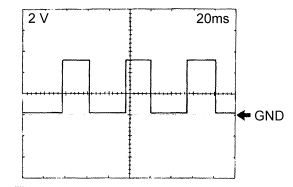
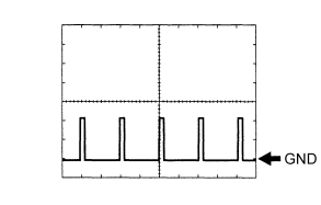
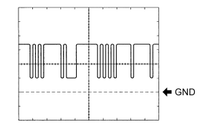
| Item | Contents |
| Measuring terminal | SPD1 ↔ GND1 |
| Instrument setting | 2V/DIV, 20ms/DIV |
| Measuring condition | Running with vehicle speed of 20 km/h |
![]()
The waveform cycle becomes shorter with increasing vehicle speed.
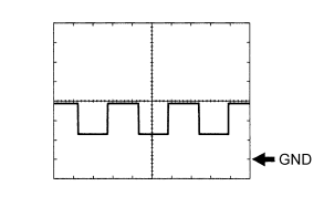
| Item | Contents |
| Measuring terminal | SL4+ ↔ SL4- |
| Instrument setting | 10V/DIV, 500ms/DIV |
| Measuring condition | Engine at idle speed |
![]()
The waveform duty ratio decreases with increasing throttle opening.
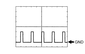
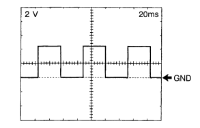
| Item | Contents |
| Measuring terminal | SP2- ↔ GND1 |
| Instrument setting | 500mv/DIV, 2ms/DIV |
| Measuring condition | Running with vehicle speed of 20 km/h |
![]()
The waveform cycle becomes shorter with increasing vehicle speed.
| Item | Contents |
| Measuring terminal | EFI- ↔ GND1, ECT- ↔ GND1 |
| Instrument setting | 1V/DIV, 2ms/DIV |
| Measuring condition | Engine at idle speed |
| Item | Contents |
| Measuring terminal | EFI+ ↔ GND1, ECT+ ↔ GND1 |
| Instrument setting | 1V/DIV, 2ms/DIV |
| Measuring condition | Engine at idle speed |
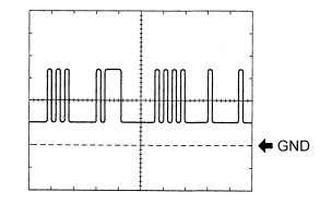
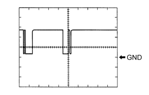
| Item | Contents |
| Measuring terminal | NT- ↔ GND1 |
| Instrument setting | 500mv/DIV, 500ms/DIV |
| Measuring condition | Engine at idle speed |
![]()
The waveform cycle becomes shorter with increasing vehicle speed.
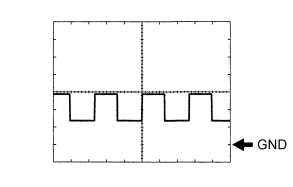
| Item | Contents |
| Measuring terminal | NE ↔ GND1 |
| Instrument setting | 2V/DIV, 20ms/DIV |
| Measuring condition | Engine at idle speed |
![]()
The waveform cycle becomes shorter with increasing vehicle speed.
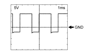
| Item | Contents |
| Measuring terminal | SIL ↔ GND1 |
| Instrument setting | 5V/DIV, 1ms/DIV |
| Measuring condition | SST connected, communication established |
![]()
The waveform cycle becomes shorter with increasing vehicle speed.