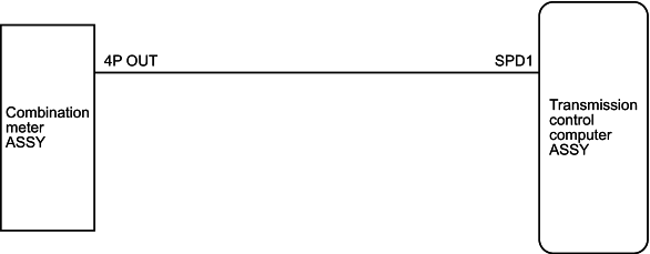
Control of shift and lock-up is performed by input of the vehicle speed signal from the combination meter ASSY to the transmission control computer ASSY.
| DTC No. |
|
Inspection part |
| P0500/42 |
|
|
Detail
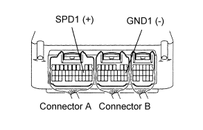
- Connect an oscilloscope between connector terminals A12 (SPD1) and B8 (GND1) of the transmission control computer ASSY.
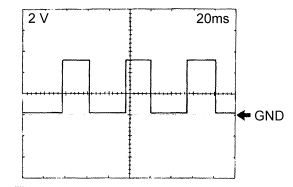
- Inspect the waveform between the terminals of the transmission control computer ASSY.
Standard:
Item Contents Measuring terminal SPD1 ↔ GND1 Instrument setting 2V/DIV, 20ms/DIV Measuring condition Running with vehicle speed of 20 km/h
The waveform cycle becomes shorter with increasing vehicle speed.
Inspect and replace the transmission control computer ASSY.
Proceed to [2]INSPECT WIRE HARNESS AND CONNECTOR (COMBINATION METER ASSY - TRANSMISSION CONTROL COMPUTER ASSY)
- Conductivity inspection
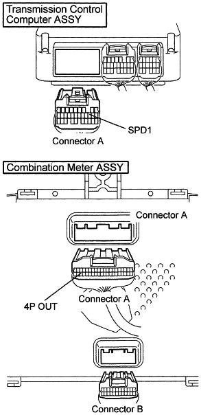
- Disconnect connector A of the transmission control computer ASSY and connector A of the combination meter ASSY.
- Check the conductivity between the connector on the wire harness side of the transmission control computer ASSY and the connector on the wire harness side of the combination meter ASSY. (Refer to page for the terminal layout.)
Standard:
Terminal No. (terminal symbol)
(Transmission computer↔meter)Conductivity A12 (SPD1) ↔ A38 (4P OUT) Yes - Insulation inspection
- Check the insulation between the connector on the wire harness side of the transmission control computer ASSY and body earth. (Refer to page for the terminal layout.)
Standard:
Terminal No. (terminal symbol)
(Transmission computer)Conductivity A12 (SPD1) ↔ Body earth No
Repair or replace wire harness and connector.
Inspect and replace the combination meter ASSY.
- Confirm the DTC P0500/42 is inactive
- Start the engine and let it idling condition.
- Verify the DTC P0500/42 is inactive.
- DTC Clear
- Clear the DTC with Hino DX
- Confirm the same DTC is not reoccurred
- P0500/42 is reoccurF Return to first process
- Other DTC appearF Refer to concerned Trouble shooting
Complete