| DTC Code |
Diag Code |
Detection Item |
Trouble Area |
| C1271 |
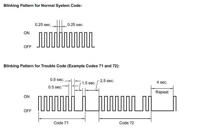
71 |
Low output signal of front speed sensor RH |
- Front speed sensor RH
- Sensor installation
-
Speed sensor rotor
|
| C1272 |
72 |
Low output signal of front speed sensor LH |
- Front speed sensor LH
- Sensor installation
-
Speed sensor rotor
|
| C1273 |
73 |
Low output signal of rear speed sensor RH |
- Rear speed sensor RH
- Sensor installation
- Speed
sensor rotor
|
| C1274 |
74 |
Low output signal of rear speed sensor LH |
- Rear speed sensor LH
- Sensor installation
- Speed
sensor rotor
|
| C1275 |
75 |
Abnormal change in output signal of front speed sensor RH |
- Front speed sensor RH
- Speed sensor rotor
|
| C1276 |
76 |
Abnormal change in output signal of front speed sensor LH |
- Front speed sensor LH
- Speed sensor rotor
|
| C1277 |
77 |
Abnormal change in output signal of rear speed sensor RH |
- Rear speed sensor RH
- Speed sensor rotor
|
| C1278 |
78 |
Abnormal change in output signal of rear speed sensor LH |
- Rear speed sensor LH
- Speed sensor rotor
|
| C1281 |
81 |
Master cylinder pressure sensor output malfunction |
- Stop light switch
- Master cylinder pressure sensor
|
| C1285 |
85 |
Vacuum sensor output malfunction |
Vacuum sensor |